

How To Register On The Dstar Gateway
What is Modbus?
Modbus is an industrial protocol standard that was created by Modicon, at present Schneider Electric, in the tardily 1970's for communication among programmable logic controllers (PLCs). Modbus remains the most widely available protocol for connecting industrial devices. The Modbus protocol specification is openly published and apply of the protocol is royalty-free.
Modbus protocol is defined as a master/slave protocol, meaning a device operating every bit a master will poll 1 or more devices operating as a slave. This means a slave device cannot volunteer information; it must wait to be asked for information technology. The master will write data to a slave device's registers, and read data from a slave device'due south registers. A annals accost or register reference is always in the context of the slave's registers.
The nigh commonly used form of Modbus protocol is RTU over RS-485. Modbus RTU is a relatively simple serial protocol that can exist transmitted via traditional UART technology. Data is transmitted in 8-bit bytes, i bit at a time, at baud rates ranging from 1200 bits per 2nd (baud) to 115200 bits per second. The majority of Modbus RTU devices but support speeds up to 38400 bits per 2nd.
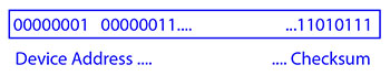
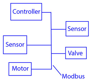
A Modbus RTU network has 1 Principal and one or more Slaves. Each slave has a unique 8-bit device accost or unit number. Packets sent past the master include the address of the slave the message is intended for. The slave must respond only if its accost is recognized, and must respond within a certain time period or the chief will call it a "no response" error.
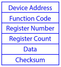
Each substitution of information consists of a request from the master, followed by a response from the slave. Each data packet, whether request or response, begins with the device accost or slave address, followed by part code, followed by parameters defining what is beingness asked for or provided. The exact formats of the request and response are documented in particular in the Modbus protocol specification. The general outline of each request and response is illustrated below.
Modbus data is about frequently read and written as "registers" which are 16-chip pieces of information. Most oft, the annals is either a signed or unsigned sixteen-scrap integer. If a 32-bit integer or floating point is required, these values are really read as a pair of registers. The most unremarkably used register is called a Holding Register, and these can be read or written. The other possible type is Input Register, which is read-only.
The exceptions to registers being 16 $.25 are the ringlet and the detached input, which are each 1 bit simply. Coils can exist read or written, while detached inputs are read-just. Coils are unremarkably associated with relay outputs.
The type of register being addressed by a Modbus asking is determined by the function lawmaking. The most common codes include 3 for "read holding registers", and may read 1 or more. Function code 6 is used to write a single holding annals. Function code xvi is used to write i or more property registers.
Visualizing Data in the Modbus Device
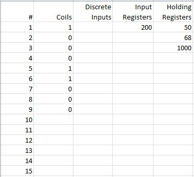
Modbus slave devices tin can be visualized as having an internal spread sheet filled with numbers. The Modbus chief will enquire a slave for its data value or number found in a given row and cavalcade, and the slave will respond by sending that piece of data back to the chief. Of class, this process tin exist reversed with the Modbus master telling the slave what number to put into its data tabular array at a given row and column.
The "columns" in a Modbus device'due south "spread sheet" are more formally known equally annals types. Register type may be a coil, a detached input (aka status input), an input register, or a holding register.
The "rows" in a Modbus device'south "spread sheet" are but the register number. Most often, these starting time at 1 and count up sequentially. Some devices might not have a register one, and their get-go annals may be number 100 for example. If the register number does not exist in the slave device, it volition send back an "oops" bulletin properly known as an exception. The exception provides an fault code that says "no such annals" (exception code 2, illegal data address).
What is Modbus TCP?
Modbus TCP encapsulates Modbus RTU asking and response information packets in a TCP packet transmitted over standard Ethernet networks. The unit number is still included and its interpretation varies past application – the unit or slave accost is not the principal means of addressing in TCP. The address of virtually importance here is the IP address, e.g. 192.168.1.100. The standard port for Modbus TCP is 502, but port number can oftentimes exist reassigned if desired.
The checksum field normally found at the end of an RTU parcel is omitted from the TCP packet. Checksum and error treatment are handled by Ethernet in the case of Modbus TCP.
The TCP version of Modbus follows the OSI Network Reference Model. Modbus TCP defines the presentation and application layers in the OSI model.
Modbus TCP makes the definition of chief and slave less obvious because Ethernet allows peer to peer communication. The definition of client and server are better known entities in Ethernet based networking. In this context, the slave becomes the server and the master becomes the client. At that place can be more than 1 customer obtaining data from a server. In Modbus terms, this means in that location tin be multiple masters too as multiple slaves. Rather than defining master and slave on a physical device past device basis, it now becomes the system designer's responsibleness to create logical associations between master and slave functionality.
What is Modbus ASCII?
Modbus ASCII is an older implementation that contains all of the elements of an RTU bundle, but expressed entirely in printable ASCII characters. Modbus ASCII is considered deprecated, is rarely used any more, and is non included in the formal Modbus protocol specification.
Review of Modbus Register Types
The types of registers referenced in Modbus devices include the post-obit:
• Coil (Discrete Output)
• Discrete Input (or Status Input)
• Input Annals
• Holding Annals
Whether a particular device includes all of these register types is up to the manufacturer. It is very common to find all I/O mapped to holding registers only. Coils are one-fleck registers, are used to command discrete outputs, and may be read or written. Discrete Inputs are 1-bit registers used as inputs, and may but be read. Input registers are 16-bit registers used for input, and may simply be read. Property registers are the virtually universal 16-bit register, may be read or written, and may be used for a diverseness of things including inputs, outputs, configuration data, or any requirement for "holding" data.
Control Solutions gateways volition support all register types when the gateway is the master, or when operating in direct mode (Babel Buster SP-GW). Control Solutions gateways that connect a non-Modbus device to a Modbus network volition in some cases use just property registers to correspond the non-Modbus device data.
Most Command Solutions I/O devices use property registers for all types of inputs and outputs. In nearly cases, the aforementioned I/O is attainable equally other register types also, with the I/O status or value beingness mirrored in multiple registers.
Review of Modbus Role Codes
Modbus protocol defines several part codes for accessing Modbus registers. In that location are four different data blocks defined past Modbus, and the addresses or register numbers in each of those overlap. Therefore, a consummate definition of where to detect a piece of data requires both the address (or register number) and function code (or annals type).
The part codes well-nigh unremarkably recognized by Modbus devices are indicated in the tabular array below. This is only a subset of the codes available - several of the codes have special applications that most ofttimes do not apply.
| Function Lawmaking | Register Type |
| 1 | Read Roll |
| two | Read Detached Input |
| 3 | Read Holding Registers |
| 4 | Read Input Registers |
| 5 | Write Single Coil |
| half dozen | Write Single Belongings Register |
| 15 | Write Multiple Coils |
| sixteen | Write Multiple Holding Registers |
Review of Modbus Exception (error) Codes
When a Modbus slave recognizes a parcel, but determines that at that place is an mistake in the asking, it volition return an exception code reply instead of a data reply. The exception reply consists of the slave address or unit number, a re-create of the part code with the high chip set, and an exception code. If the role code was iii, for case, the role code in the exception answer will be 0x83. The exception codes volition be one of the following:
| 1 | Illegal Function | The part code received in the query is not recognized past the slave or is not allowed by the slave. |
| 2 | Illegal Data Address | The data address (register number) received in the query is non an immune accost for the slave, i.eastward., the register does not exist. If multiple registers were requested, at least one was not permitted. |
| three | Illegal Information Value | The value independent in the query's data field is non acceptable to the slave. |
| four | Slave Device Failure | An unrecoverable error occurred while the slave was attempting to perform the requested action |
| 6 | Slave Device Busy | The slave is engaged in processing a long-duration command. The master should endeavour again later on. |
| 10 | Gateway Path Unavailable | Specialized use in conjunction with gateways, usually means the gateway is misconfigured or overloaded |
| 11 | Gateway Target Device Failed to Respond | Specialized employ in conjunction with gateways, indicates no response was received from the target device. |
Where do I Start for Communicating with My Modbus Device?
Hither are the start few things you need to find out:
(1) What is the physical connexion?
Modbus RTU uses RS-485 or RS-232. Modbus TCP uses Ethernet. If you are looking for a Control Solutions gateway, you will need to pick the model that matches the electrical interface of the equipment you want to connect. If you are choosing a Control Solutions I/O device, pick one that matches your network.
(ii) How are the registers mapped?
When using a gateway to interface a Modbus device to a not-Modbus network, you demand to get documentation from the equipment manufacturer that describes the bachelor registers and how to accost them. Modbus protocol does non provide a means for registers to automatically identify themselves. Command Solutions cannot make up one's mind this information for you lot. You lot must consult the equipment manufacturer.
When using Control Solutions I/O devices (such as AddMe 3) you lot will find this information in the online help files that came with the device, or on our web site.
(iii) What are the advice parameters?
Modbus RTU requires that y'all know or ascertain baud rate, character format (8 bits no parity, etc), and slave ID (aka slave address, unit number, unit ID). A mis-friction match in any of these volition upshot in no advice.
Modbus TCP requires that you know or define IP addresses on the network. In some cases, you lot as well need unit of measurement ID'due south. Command Solutions Modbus TCP devices may use the unit of measurement ID, or may ignore it, depending on the device and the application.
Modbus: When 40001 Really Ways 1, or 0 Really Means i
Documentation for Modbus is not well standardized. Actually in that location is a standard, but not well followed when information technology comes to documentation. Yous will have to practise 1 or more of the following to decipher which register a manufacturer is really referring to:
a) Await for the annals description, such every bit holding annals, roll, etc. If the documentation says #1, and tells you they are holding registers, then you have belongings annals #1. Y'all also have user friendly documentation.
b) Look at the numbers themselves. If you run across the beginning annals on the list having a number 40001, that really tells you register #one, and information technology is a holding register. This class of notation is frequently referred to as the old Modicon convention.
c) Look for a definition of function codes to exist used. If you see a annals #1, along with notation telling you to use function codes iii and xvi, that also tells you it is holding annals #i.
Of import: Register i is address 0. Read on…
d) Do the numbers in your documentation refer to the register number or accost? Annals #ane is address zero. If it is not articulate whether your documentation refers to register or address, and you are not getting the expected result, effort plus or minus 1 for annals number. All Control Solutions products refer to annals numbers in configuration software or web pages. However, some manufacturers document their devices showing address, non register numbers. When you have addresses, you must add together one when entering that register into configuration software from Control Solutions.
40001: Modicon Convention Notation for Modbus Registers
Modbus was originally adult by Gould-Modicon, which is presently Schneider Electric. The annotation originally used by Modicon is yet often used today, even though considered obsolete by nowadays Modbus-IDA standards. The advantage in using the Modicon notation is that two pieces of information are included in a single number: (a) The register blazon; (b) The register number. A annals number get-go defines the type.
Note: Only the LonWorks versions of Babel Buster gateways employ this notation equally short hand to conserve CP space. Many other equipment manufacturers still use this convention in their products. Depending on which combination of products yous are using, yous may have to interpret between Modicon and current conventions.
The types of registers referenced in Modbus devices, and supported past Babel Buster gateways, include the following:
• Whorl (Discrete Output)
• Detached Input (or Condition Input)
• Input Register
• Belongings Register
Valid address ranges as originally divers for Modbus were 0 to 9999 for each of the higher up register types. Valid ranges allowed in the current specification are 0 to 65,535. The address range originally supported by Babel Buster gateways was 0 to 9999. The extended range addressing was later added to all new Boom-boom Buster products.
The address range applies to each blazon of register, and one needs to look at the role code in the Modbus message bundle to determine what register blazon is beingness referenced. The Modicon convention uses the first digit of a register reference to place the register type.
Register types and reference ranges recognized with Modicon notation are as follows:
0x = Coil = 00001-09999
1x = Discrete Input = 10001-19999
3x = Input Register = 30001-39999
4x = Holding Register = 40001-49999
On occasion, information technology is necessary to admission more than 10,000 of a annals blazon. Based on the original convention, in that location is another de facto standard that looks very similar. Additional register types and reference ranges recognized with Modicon notation are as follows:
0x = Coil = 000001-065535
1x = Detached Input = 100001-165535
3x = Input Register = 300001-365535
4x = Holding Register = 400001-465535
When using the extended register referencing, it is mandatory that all register references be exactly 6 digits. This is the simply way Boom-boom Buster volition know the difference between holding register 40001 and coil 40001. If coil 40001 is the target, it must announced as 040001.
Registers Are 16-bits - How Do I Read Floating Signal or 32-bit Information?
Modbus protocol defines a holding register as 16 $.25 wide; however, there is a widely used de facto standard for reading and writing information wider than xvi bits. The most common are IEEE 754 floating bespeak, and 32-bit integer. The convention may also exist extended to double precision floating indicate and 64-flake integer data.
The wide data simply consists of two consecutive "registers" treated every bit a unmarried wide register. Floating point in 32-bit IEEE 754 standard, and 32-bit integer data, are widely used. Although the convention of register pairs is widely recognized, agreement on whether the high order or low order register should come first is not standardized. For this reason, many devices, including all Control Solutions gateways, support a "swap" option. This means you only check the "swapped" option if the other device treats wide information in the contrary lodge relative to Command Solutions default society. In some cases, the "swap" choice is more explicitly identified as "loftier club data is in first register" or something to that issue.
Most Command Solutions Modbus products default to placing the high order annals first, or in the lower numbered register. This is known equally "large endian", and is consistent with Modbus protocol which is past definition large endian itself. The byte order for all 16-bit values is most meaning byte starting time.
What Does Notation Like 40001:7 Mean?
This is a commonly used notation for referencing individual bits in a annals. This particular instance references (Modicon notation) register 40001, bit 7. Bits are generally numbered starting at bit 0, which is the to the lowest degree significant or right most bit in the field of 16 bits establish in a Modbus register. If this style notation is used, yous may see 40001:0 through 40001:15.
How Do I Read Individual $.25 in a Register?
Documentation tends to be slightly unlike for every Modbus device. But if your device packs multiple bits into a unmarried holding register, the documentation will annotation upwardly to sixteen different items plant at the same register number or accost. The bits may be identified with "Bn" or "Dn" or just "scrap due north". About of the time, the least significant bit volition be chosen chip 0 and the near significant volition be flake fifteen. It is possible you could find reference to flake 1 through bit 16, in which example merely subtract one from the number to reference the table beneath.
You cannot read only one fleck from a property register. There is no way to do that - Modbus protocol simply does not provide that function. You must read all 16 $.25, and then test the private flake you are interested in for true or false (one or 0). Boom-boom Buster gateways provide an automated mode of doing that past including a "mask" in each annals map or rule. Each time the register is read, the mask will exist logically AND-ed with the data from the annals, and the event will be right justified to yield a 1 or 0 based on whether the selected bit was i or 0. Babel Buster gateways provide optimization when successive read maps or rules are selecting dissimilar bits from the same register. The Modbus register will be read from the slave in one case, and the xvi-flake data will be shared with successive maps or rules, with each map or dominion selecting its flake of interest.
The fleck mask shown in the expanded form of the Babel Buster RTU read map is a four digit hexadecimal (xvi bit) value used to mask out one or more bits in a register. The selected $.25 volition be correct justified, then a single bit regardless of where positioned in the source register will be stored locally every bit 0 or 1. The hex bit mask values would be as follows:
B0/D0/flake 0 mask = 0001
B1/D1/bit one mask = 0002
B2/D2/fleck two mask = 0004
B3/D3/bit 3 mask = 0008
B4/D4/bit iv mask = 0010
B5/D5/chip 5 mask = 0020
B6/D6/bit 6 mask = 0040
B7/D7/flake 7 mask = 0080
B8/D8/bit 8 mask = 0100
B9/D9/flake 9 mask = 0200
B10/D10/bit ten mask = 0400
B11/D11/flake 11 mask = 0800
B12/D12/flake 12 mask = 1000
B13/D13/bit 13 mask = 2000
B14/D14/bit 14 mask = 4000
B15/D15/bit 15 mask = 8000
Some Modbus devices also back two 8-bit values into a single 16-bit annals. The ii values will typically exist documented as "loftier byte" and "low byte" or simply have "H" and "Fifty" indicated. If you run into this scenario, the masking for bytes is as follows:
High byte mask = FF00
Low byte mask = 00FF
When the mask value in a Babel Buster gateway is more just one scrap, the mask is still logically AND-ed with the data from the Modbus slave, and the entire resulting value is right justified to produce an integer value of less than the original bit width of the original annals.
At that place have been a few instances of documenting packed bits in a 32-bit register. Although Modbus protocol is strictly 16-chip registers, some implementations strength yous to read pairs of registers. If your device documents 32 packed $.25, and then yous would insert 0000 in front of each mask above, and the remainder of the list would be equally follows:
B16/D16/fleck 16 mask = 00010000
B17/D17/flake 17 mask = 00020000
B18/D18/bit 18 mask = 00040000
B19/D19/bit 19 mask = 00080000
B20/D20/flake xx mask = 00100000
B21/D21/bit 21 mask = 00200000
B22/D22/bit 22 mask = 00400000
B23/D23/flake 23 mask = 00800000
B24/D24/chip 24 mask = 01000000
B25/D25/fleck 25 mask = 02000000
B26/D26/bit 26 mask = 04000000
B27/D27/bit 27 mask = 08000000
B28/D28/bit 28 mask = 10000000
B29/D29/flake 29 mask = 20000000
B30/D30/bit thirty mask = 40000000
B31/D31/bit 31 mask = 80000000
Tin I Put 2 Gateways on the Aforementioned Modbus Network?
You can non have more than one Chief on a Modbus RTU (RS-485) network. Therefore, if the gateway is to be configured equally the Master, y'all can only have 1 gateway. You cannot employ multiple gateways to read more points from the same Modbus slave device.
Multiple gateways configured as slaves can reside on the same Modbus RS-485 network.
If you are using RS-232 devices, you lot tin have only two devices total, regardless of how they are configured. RS-232 is not multi-drop.
How Many Devices Can I Have on a Modbus Network?
Logically you can address over 250 devices; yet, the RS-485 transceivers are not capable of physically driving that many devices. Modbus protocol states that the limit is 32 devices, and most RS-485 transceivers will agree with this. Simply if all devices on the network have low load transceivers can you lot take more than 32 devices.
Where Can I Go a Copy of the Modbus Protocol Specification?
You lot tin can get a copy of the Modbus protocol specification by visiting www.modbus.org. There are three documents of primary interest: (1) The application layer protocol which defines the part codes and addressing; (2) The definition of apply over a serial line (RTU); (three) The definition of utilise over Ethernet (TCP). Yous will be asked to have terms of use, but at that place is no cost for these specifications.

Source: https://www.csimn.com/CSI_pages/Modbus101.html
Posted by: lawsoncaph1956.blogspot.com
0 Response to "How To Register On The Dstar Gateway"
Post a Comment